



Injection Molding Guide: Process, Design Tips, & Materiales
Learn how injection molding works, when to use it, and how to design moldable plastic parts for better results
Injection molding is behind countless plastic parts in your daily life, from the keys on your keyboard to the housing on a medical device. It is everywhere because it can produce the same part again and again with speed and consistency.
It can be expensive to start, but cost-effective to scale. Compared with CNC machining or 3D printing, injection molding requires more upfront investment because a mold has to be made first. Once that tool is built, though, the cost per part can drop significantly, making it ideal for production runs, bridge tooling, and end-use plastic parts.
That repeatability is exactly why design choices are so critical. A smart design choice can improve thousands of parts. A bad one can create sink marks, warping, cosmetic defects, or tooling headaches just as quickly. Design for injection molding means thinking about wall thickness, draft, ribs, bosses, gates, material choice, surface finish, and ejection before resin ever hits the mold.
This guide covers the basics of plastic injection molding, how the process works, common types of injection molding, and the best practices that help improve part quality.
What is Injection Molding?
Injection molding is a manufacturing process for producing finished parts from plastic, elastomeric, or other moldable materials. In plastic injection molding, resin is melted, injected into a metal mold cavity, cooled, and ejected as a solid part.
The process is widely used for plastic parts because it can produce consistent results with low material waste and low cost per part. You'll find injection-molded components across industries such as medical devices, aerospace, automotive, robotics, consumer electronics, and industrial equipment.
Depending on where a part is in development, Protolabs can support prototyping, production injection molding, and on-demand production with no minimum order quantity. Parts can be delivered as fast as one day, depending on the project. Its plastic injection molding capabilities support parts up to 18.9 in. by 29.6 in. by 8 in. (480mm by 751mm by 203mm). For more detail on draft, radii, wall thickness, and moldability analysis, see Protolabs’ guide to injection molding basics.
How Does Injection Molding Work?
Injection molding works in two stages: making the mold and producing the parts. First, a mold is designed and manufactured around the part geometry. The mold includes the cavity that forms the part, along with gates, runners, cooling channels, ejector pins, and any features needed to release the part.
Once the mold is ready, the molding cycle follows a sequence: clamp the mold, inject molten resin, cool the part, eject it, and repeat. Even in this simple cycle, small design choices can affect fill, cooling, shrink, cosmetics, and repeatability. Protolabs’ aluminum mold tooling options can support different stages of development, from early validation through production.
This video walks you through the basics.
Types of Injection Molding
Different injection molding processes support different part designs, materials, and production goals.
| Type | Best For | Design Considerations |
|---|---|---|
| Thermoplastic injection molding | Plastic prototypes and production parts | Material selection, wall thickness, shrink, draft, and part geometry drive moldability |
| Liquid silicone rubber molding | Flexible, durable, heat-resistant parts | Useful for seals, gaskets, medical components, and soft-touch applications |
| Overmolding | Multi-material parts | Requires compatibility between substrate and overmold material |
| Insert molding | Parts with metal inserts, threaded features, or electrical components | Insert placement, retention, and molding pressure must be considered early |
| Family and multi-cavity molding | Multi-part or multi-cavity production runs | Multiple parts molded together in one tool to reduce cost and lead time |
| Production injection molding | Higher-volume production | Multi-cavity tooling and production planning can reduce part cost over time |
Design for Injection Molding: Best Practices
The right approach to injection molding design helps parts fill, cool, and eject cleanly. Protolabs’ plastic injection molding design guidelines can help you pressure-test the details before tooling begins.
- Keep wall thickness consistent: Thick sections cool more slowly than thin sections, which can lead to sink, voids, and warping, so follow wall thickness guidelines that keep walls within 40% to 60% of adjacent thickness and inside the recommended range for the selected resin.
- Core our unnecessary mass: Cored geometry can reduce cooling variation, sink, part weight, and secondary machining without changing the part’s basic function.
- Add draft early: Draft helps parts release cleanly from the mold. A common starting point is 1 to 2 degrees, with more draft for textured surfaces. These draft angle guidelines explain how draft affects molded part quality and mold release.
- Use rubs and gussets for strength: Thin supporting features can add stiffness without the sink risk of thick solid sections. A common guideline is to keep ribs around 60 percent.
- Plan gates and runners around flow and cosmetics: Gate location affects fill, pressure, weld lines, and visible gate marks, so careful gate planning can improve moldability and reduce cosmetic issues.
- Account for ejection and undercuts: Ejector pins can leave marks, while undercuts may require side-actions, pickouts, sliding shutoffs, or design changes.
- Use tight tolerances only where needed: Resin shrink, cooling, part geometry, and tool design all affect final dimensions. Protolabs’ injection molding process can hold about ±0.003 in. machining accuracy, while shrink tolerance can range from 0.002 in./in. for stable resins like ABS and polycarbonate to 0.025 in./in. for less stable resins like TPE. If tight tolerances, complex geometry, or critical features are involved, mold flow analysis can help identify potential issues before tooling.
For a hands-on reference, our Design for Moldability Toolkit shows common molded part features such as thin walls, thick sections, bosses, ribs, and other design details.

Clips and Snap Fits
Clips and snap fits can reduce the need for screws, adhesives, and secondary hardware. The trade-off is that they add stress and flex to the design, so you’ll have to carefully consider your material choice. A flexible resin may work well for a snap feature, while a stiff or brittle material may crack. Depending on the geometry, the mold may also need shutoffs, side-actions, or a redesign to release the part cleanly
Living Hinges
Living hinges are thin, flexible sections of plastic that let two molded sections bend repeatedly. Polypropylene is often a good material for this because it can flex many times without failing quickly. Keep the hinge thin, consistent, and free of sharp transitions, and consider gate location because resin flow can affect hinge performance.

Bosses and Standoffs
Bosses and standoffs are common in assemblies that use screws, inserts, pins, or locating features. The main risk is making them too thick. Core out solid bosses, support them with ribs or gussets where needed, and keep the surrounding wall thickness as consistent as possible to reduce sink and voids.
Text on Parts
Molded text needs to be large enough to machine, fill, and eject cleanly. Simple sans serif fonts are usually easiest to mill into the mold. As a general rule, use fonts larger than 20 pt., keep text to between 0.010 in. and 0.015 in. deep, and make the smallest stroke at least 0.020 in. wide.

Overmolding
Overmolding combines two materials into one part, such as a rigid plastic substrate with a softer grip, seal, or cushion. A successful overmolded part depends on material compatibility, bonding, and geometry. For multi-material design guidance, see these overmolding and insert molding design guidelines.
Common Injection Molding Defects and Design Fixes
Some molding defects can be adjusted during production, but many start with the part design. Building in good moldability from the start can help reduce common injection molding defects.
| Defect | What It Looks Like | Common Design Cause | Design Fix |
|---|---|---|---|
| Sink marks | Depressions on the surface | Thick walls, heavy bosses, thick ribs | Core out thick areas and use ribs instead of solid mass |
| Warping | Twisted, bowed, or uneven part | Uneven wall thickness, cooling imbalance, high shrink | Use consistent wall thickness and gradual transitions |
| Voids | Internal air pockets | Thick sections that cool unevenly | Reduce thick areas and avoid unnecessary mass |
| Flash | Thin excess plastic at edges or parting lines | Poor shutoff design, difficult parting line | Improve shutoffs and review parting line placement |
| Short shots | Incomplete fill | Thin walls, long flow paths, poor gate location | Improve wall thickness, flow paths, or gate placement |
| Jetting | Wavy or worm-like surface marks | Resin enters too quickly into open space | Adjust gate location or geometry to improve flow |
Our online platform includes manufacturing analysis that can help identify design risks that lead to defects, including thick sections, undercuts, gate locations, and ejector pin placement.
Material Selection for Injection Molding
The right material depends on what the part needs to do, from strength and flexibility to heat resistance, chemical resistance, shrink, finish, and cost. Colorants and additives can change how a resin molds, looks, and performs, so factor them into material selection. This injection molding material selection guide goes deeper on those trade-offs.

| Material Type or Family | Common Examples | Best For | Design Considerations |
|---|---|---|---|
| Thermoplastic commodity resins | PP, PE, PS | Cost-sensitive parts, containers, simple housings | Lower cost, but performance varies by resin |
| Thermoplastic engineering resins | ABS, PC, nylon, acetal/POM, PBT | Functional parts, housings, gears, clips | Better strength, heat resistance, or dimensional stability |
| Thermoplastic high-performance resins | PEEK, PEI, PPS | Thermal, chemical or mechanical demands | Higher cost; may need tighter design review |
| Thermoplastic elastomers | TPE, TPU | Flexible grips, seals, and soft-touch features | Processes like thermoplastics but provide elastomer-like flexibility |
| Liquid silicone rubber | LSR | Seals, gaskets, medical components, and flexible parts | Elastomeric material with different molding, finish, and release considerations |
Protolabs stocks 100+ plastic and elastomeric materials, and Protolabs Network can source thousands more by request.
Surface Finishes for Molded Parts
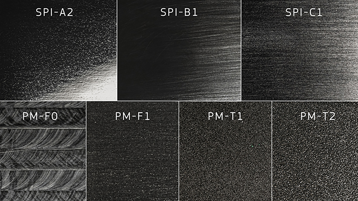
For standard molded finishes, the mold surface largely determines the part surface. Polished and bead-blasted finishes are applied to the tool and transferred to the molded part, so surface finish can affect appearance, draft, material choice, and how easily the part releases from the mold. Protolabs’ guide to injection molding surface finishes explains the available finish options in more detail.
| Finish Category | Thermoplastic Options | LSR Options | Best For |
|---|---|---|---|
| Non-cosmetic | PM-F0, PM-F2 | PM-F0 | Internal or functional parts where appearance is not critical |
| Low-cosmetic | PM-F1 | PM-F1 | Functional prototypes or less visible surfaces |
| Polished | SPI-C1, SPI-B1, SPI-A2 | SPI-C1, SPI-A2 | Clear, glossy, or cosmetic surfaces. Glass- and mineral-filled resins can show streaking on polished finishes |
| Bead-blasted texture | PM-T1, PM-T2 | PM-T1, PM-T2 | Matte appearance, light-to-medium texture, or hiding minor cosmetic marks. Plan for at least 3 degrees of draft for PM-T1 and 5 degrees for PM-T2 |
For more complex cosmetic textures, Mold-Tech-style finishes can create effects such as pebbled, grained, leather-like, or other patterned surfaces.
If the part has cosmetic requirements, align the finish with the material, color, geometry, and draft before tooling moves forward. Darker colors tend to show texture more clearly than lighter colors, and this guide to cosmetic appearance on molded parts goes deeper on finish, material, and color choices.
Post-Processing and Advancing Molding Techniques
Some injection-molded parts need extra steps or tooling features to support assembly, marking, or complex geometry. These secondary operations can add functionality, but they can also affect part design, tooling, cost, and lead time.
- Use ultrasonic welding when molded parts need to be fused together or when inserts need to be driven into plastic with heat and vibration. A welded part may need an energy director, while an insert needs enough surrounding material for support.
- Use part marking when a molded part needs a logo, instructions, or other identification. Pad printing can add color graphics to compatible resins, while laser engraving burns a permanent 2D image into the part or mold cavity without adding color.
- Use pickouts when interior undercuts cannot be released automatically. They can solve geometry problems, but they can also add more cost and handling than sliding shutoffs or side-actions.
- Use steel core pins when the design needs clean holes without draft. Any cosmetic effect is usually hidden inside the hole.
Quality Control and Certifications
Injection molding quality depends on part design, mold design, material selection, process control, and inspection. At production volumes, quality is about consistency and meeting the same requirements across thousands, or even millions, of units. Protolabs uses digital processes, scientific molding, and inspection reporting to support injection molding quality at scale.
| Quality Option | What It Helps Confirm | |
|---|---|---|
| First Article Inspection | Initial parts match specified dimensions | |
| PPAP | The production process can repeatedly meet requirements | |
| Scientific molding | Process parameters are controlled and repeatable | |
| CMM inspection | Critical dimensions are measured accurately | |
| CTQ inspections | Features critical to function are checked consistently | |
| Material and inspection documentation | Parts meet project, regulatory, or supply chain requirements | |
Production is backed by ISO 9001:2015 and ITAR registration, with ISO 13485 available through Protolabs Network for medical applications.
Prototyping projects come with a Quality Inspection Report (QIR) as a baseline dimensional check. For projects that need more documentation, Protolabs' injection molding inspections include options such as standard inspection, Critical to Quality inspection, and advanced inspection reporting.
Injection Molding Glossary: Terms to Know
- Boss: A raised feature used for fasteners, inserts, pins, or alignment.
- Core out: Remove unnecessary material from a thick section while keeping the part's function.
- Draft: A slight angle added to vertical walls so the part can release cleanly from the mold.
- Ejector pins: Pins that push the finished part out of the mold after cooling.
- Gate: The opening where molten resin enters the mold cavity.
- Gusset: A support feature that reinforces walls, bosses, or other raised geometry.
- Parting line: The line where the two halves of the mold meet.
- Pickout: A removable mold insert used to form difficult features that cannot release automatically.
- Rib: A thin support feature used to add strength or stiffness without making the whole wall thicker.
- Runner: A channel that carries resin from the injection point to the gate.
- Shutoff: An area where two mold surfaces meet to form a feature, often used to avoid or simplify side-actions.
- Side-action: A moving mold component used to form or release features that are not aligned with the mold opening direction.
- Sink mark: A small surface depression caused by uneven cooling or thick material sections.
- Undercut: A feature that prevents the part from being pulled straight out of the mold.
- Weld line: A visible or structural line where two resin flow fronts meet inside the mold.
Frequently Asked Questions
What makes a part suitable for injection molding?
expand_less expand_moreA good injection-molded part has consistent wall thickness, enough draft, realistic tolerances, and geometry that can release cleanly from the mold.
How can you reduce the cost of an injection-molded part?
expand_less expand_moreYou can often reduce cost by simplifying geometry, avoiding unnecessary side-actions, using consistent wall thickness, choosing the right resin, and designing for efficient molding from the start.
What causes warping in injection-molded parts?
expand_less expand_moreWarping is often caused by uneven wall thickness, uneven cooling, material shrink, or geometry that creates internal stress as the part cools.
How much draft does an injection-molded part need?
expand_less expand_moreA common starting point is 1 to 2 degrees of draft, with more draft for textured surfaces or deeper features that need extra help releasing from the mold.
What is the difference between a side-action and a pickout?
expand_less expand_moreA side-action is a moving mold component that automatically slides in and out during each cycle to form or release an undercut feature. A pickout is a removable mold insert that is manually removed after each shot. Side-actions add tooling cost but are faster in production; pickouts are simpler but slower.
When should I use insert molding instead of overmolding?
expand_less expand_moreUse insert molding when you need to embed a component, often metal, into a plastic part for strength, conductivity, or thread integrity. Use overmolding when you want to combine two plastic or elastomeric materials for grip, cushioning, or sealing.
Get injection-molded parts
| Ready to turn these design tips into finished parts? Upload your CAD file for an instant injection molding quote and manufacturability feedback. |